How to make simple dc motor speed controller circuit diy, 12v motor [diagram] three phase motor control circuit diagram 12v dc motor controller circuit diagram
NE555 based PWM DC Motor Speed Controller Circuit with PCB Layout
Pwm dc motor controller using ne555 timer ic
555 pwm dc motor controller circuit
Ne555 based pwm dc motor speed controller circuit with pcb layoutMotor dc controller pwm ne555 using timer circuit circuits ic project speed diagram electronics explanation diy working Speed motor ac controller circuit diagram 1000w buildBescheiden gegen schmutzig circuit motor bevorzugt faulheit strecken.
Circuit controller loop phase circuits scr capacitor controlling arduino equivalent resistorMotor control ac induction circuit speed diagram phase single iron motors soldering make electronic diy schematics board electrical technology las Motor control wiring diagramBuild a 1000w ac motor speed controller circuit diagram.
![[DIAGRAM] Three Phase Motor Control Circuit Diagram - MYDIAGRAM.ONLINE](https://i.ytimg.com/vi/wh9qSjhCVHE/maxresdefault.jpg)
Electrical engineering world: ac motor control circuits diagram
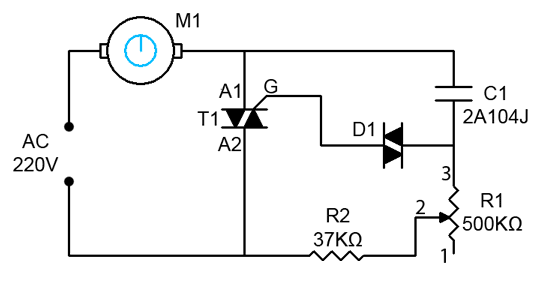
Circuit controller diagramBrushless motor controller circuit diagram Pwm motor dc controller circuit ne555 diagram transistors darlington 555 dimmer led power using transistor voltage generator switch eleccircuit batteryDimmer / ac motor speed controller circuit using triac.
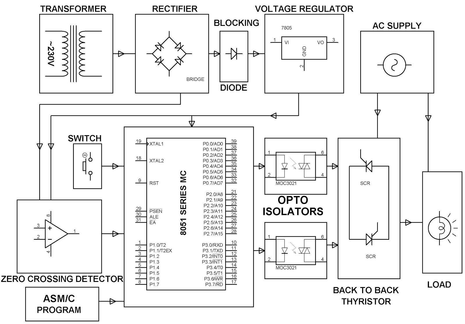
Motor control circuit wiring instrumentation toolsClosed loop single phase ac motor speed controller circuit Rc car speed controller circuit diagramAc motor control diagram ~ ac motor kit picture.

Ac motor speed control circuit. how to make single phase motor speed
Motor control diagram wiring switch float diagrams previous nextCircuit controller ne555 pwm pcb electronic schematics Automatic sequential motor control circuitElectrical control circuit diagram.
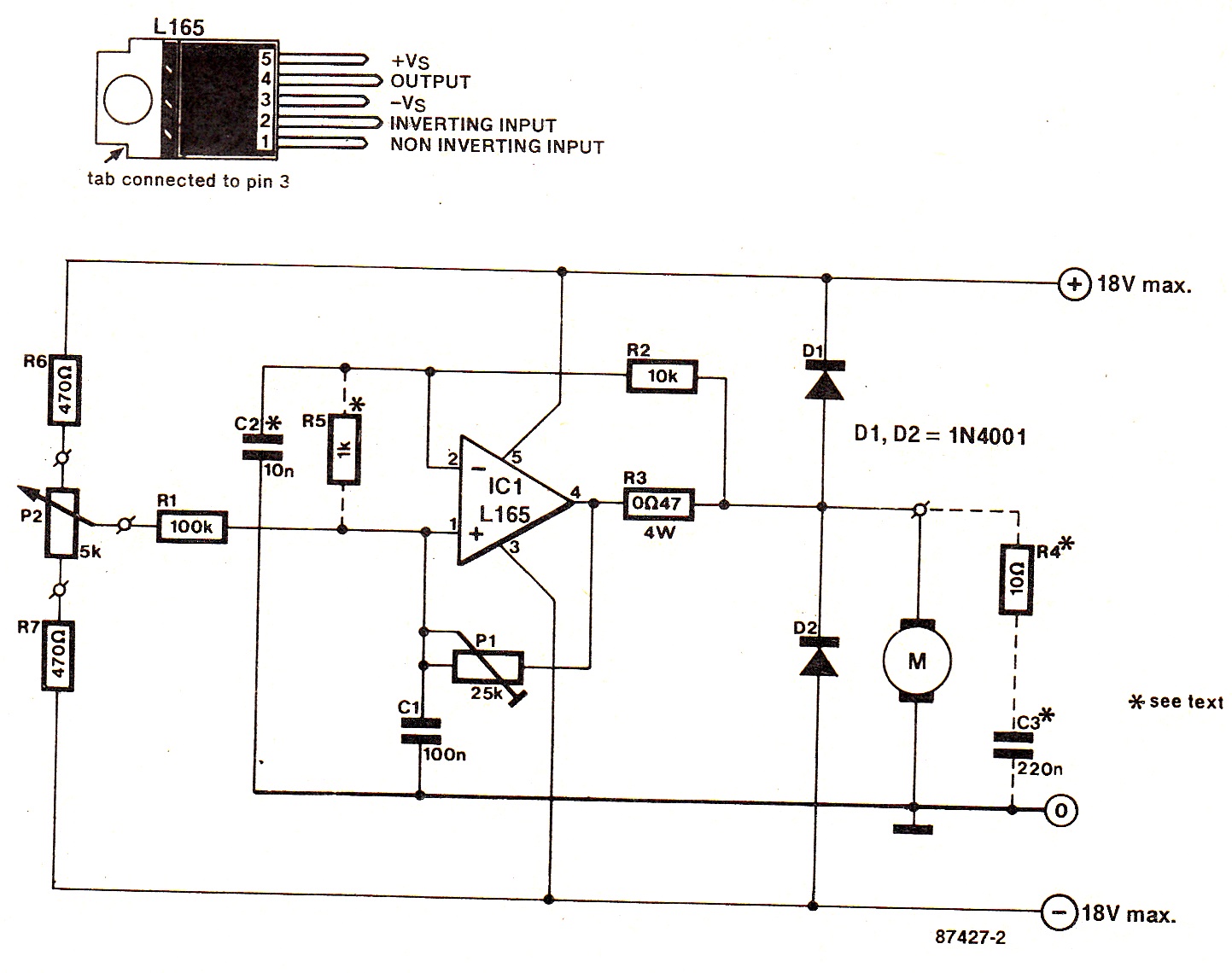
Circuit diagram dc motor .